The evolution towards open cables
With a typical cable having an engineering design life of at least 25 years, it’s not surprising that a given cable will have the opportunity to use several generations of transponder technology over its lifetime.
June 7, 2021

Telecoms.com periodically invites expert third parties to share their views on the industry’s most pressing issues. In this piece Vincent Gatineau, Chief Marketing and Sales Officer for EllaLink, and Geoff Bennett Director of Solutions & Technology for Infinera, explore the evolution of submarine cables.
From Closed to Open Cable Systems
There are over 400 submarine communication cables deployed under the seas and oceans of the world today. With a typical cable having an engineering design life of at least 25 years, it’s not surprising that a given cable will have the opportunity to use several generations of transponder technology over its lifetime.
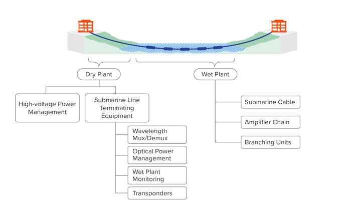
Or will it? Figure 1 shows the building blocks of a submarine cable system, showing the breakdown of the wet plant (cable, amps, branching units) and the dry plant (high- voltage management, wave mux/demux – usually a ROADM today, wet plant monitoring, optical power management, and transponders). When submarine cables were first deployed, it was common practice to have a single prime contractor for the entire system, including the transponders, and contractual language would typically restrict the cable operator to buying the transponder technology from that prime contractor.
For many years this was simply accepted as “the way we do things” in the submarine communications world, but that began to change around the year 2009 when terrestrial transponder vendors showed that their equipment would work just fine over existing, dispersion-managed submarine cables (see sidebar), and that they could offer those transponders at lower prices and with shorter lead times than the legacy suppliers. That was still the era of 10 Gb/s per wavelength, non-coherent transmission, but the trend really began to accelerate when coherent transponders demonstrated a 4X to 10X increase in wavelength data rates (to 40 Gb/s or 100 Gb/s per wavelength), and a similar factor increase in fiber capacity.
Submarine Cable Evolution
The first submarine cables were used with direct-detection transponders that were susceptible to chromatic dispersion. Several generations of “dispersion-managed” cables – with alternating lengths of positive and negative dispersion fiber types along the length of the cable – were developed and deployed. These cables maintain an average dispersion level around zero.
But coherent technology includes electronic dispersion compensation and operates with lower nonlinear penalties if there is a lot of chromatic dispersion in the fiber. So, from about 2012, we see the emergence of “uncompensated” cables designed for coherent transmission. Coherent transponders work well with all cable types but will deliver significantly higher performance in uncompensated cables.
Only a small number of optical equipment vendors were able to invest in coherent technology, and this period (around 2012) also saw a dramatic rise in the importance of the hyperscale internet content providers (ICPs) as not only consumers of submarine network capacity but also active participants in cable consortia. ICPs were already leading the charge toward disaggregated, open standard solutions within the data center as well as over their terrestrial networks between data centers.
They began to consider the submarine network link as an extension of that open network architecture, and part of that vision was for submarine cables to be “open” – with no obligations (neither technical nor commercial) to use a given transponder type. At that stage there was gradual and, in some cases, reluctant participation by wet plant vendors toward this process, but eventually it became more practical for third-party wet plant monitoring equipment to operate with most of the legacy wet plant deployed. Thanks to a general acceptance of the value of open cables, new cable systems from 2012 onward were almost all designed from scratch to be open, and with commercial terms that allowed a flexible choice of transponders.
Open Cables vs. Spectrum Sharing
A typical submarine cable will contain multiple fiber pairs, and a simplistic definition of an open cable would be one that allows a cable operator to select the best-of-breed transponders to operate over a given fiber pair. Thus, if a given cable has four fiber pairs, one can imagine up to four different brands of transponders deployed on the cable. The assumption here is that the “openness” of the cable is at the granularity of the fiber pair.
The capacity of a given fiber pair on a submarine cable varies dramatically with the type and length of cable and the generation of transponders, but for modern cable types with trans-Atlantic reach, it would be quite reasonable to expect a capacity of up to 25 Tb/s per fiber pair using the latest fifth-generation transponder technology. In the past it would have been traditional to terminate the optical path of the submarine cable using an OTN switch in the cable landing station. In addition to regenerating the signal, the OTN switch can divide up the fiber pair capacity, act as a service demarcation point, provide sub-50-ms service protection, and enable sophisticated digital monitoring. But using OTN switches on modern fiber pairs with tens of terabits of capacity per fiber pair could result in massive equipment cost, and considerable requirements for rack space, power, and cooling. These may simply be unavailable in some CLS locations, and will add a small amount of latency.
Modern compact modular platforms can replace the monitoring function, a flexible-grid ROADM is used to partition spectrum capacity in the all-optical domain and provide demarcation points, and the latest coherent transponders can deliver the optical performance needed to drive the signal onward from the CLS to a more convenient data center location that is designed for the scale of space and power needed.
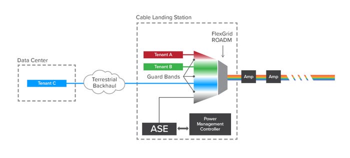
Figure 2 illustrates some of the options. We can see how the spectrum of a single fiber pair is divided and can be sold as a “virtual fiber pair” to multiple operators. These operators can choose to have a demarcation point in the CLS (shown for Tenants A and B) or to continue the optical path directly to the data center (shown for Tenant C). As you can imagine, it’s not quite as simple as just saying yes to whichever transponders are being deployed. The key point in a shared-spectrum cable is how the cable operator can ensure that all the services operating in a given spectrum slice are just as reliable, stable, and independent from each other as if they were operating on dedicated fiber pairs. To understand how this is achieved, we need to take a closer look at how submarine amplifiers operate, which will in turn explain the need for intelligent optical power management.
Intelligent Power Management
Submarine amplifiers are designed to operate in constant power mode. What that typically means is that the power level of the amps is carefully adjusted to deliver the required gain across the whole spectrum, assuming all optical channels are in use. Figure 3 shows how a set of eight wavelengths enters a submarine amplifier and is boosted so that all wavelengths are still below the nonlinear threshold.
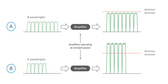
If the amplifier does not receive all the wavelengths that it expects for some reason, it will still apply the same total power, but this is now shared between fewer wavelengths. The end result is that each wavelength will experience more gain, and this may result in exceeding the nonlinear threshold. This is shown in Figure 3B, where three of the eight wavelengths disappear, and the remaining five wavelengths are now operating beyond the nonlinear threshold. Since there may be several dozen transponders operating across a given fiber pair, the loss (or addition) of one or two would not usually cause a problem. It’s when multiple transponders “disappear” in a single event that can cause instability. So how could that happen?
In Figure 2 we saw a shared-spectrum fiber pair with three tenants allocated different sizes of spectrum that each form a virtual fiber pair, guard bands maintained between the virtual fiber pairs, and unallocated spectrum that is filled with optical power from a modified optical amplifier that is configured to generate amplifier spontaneous emission (ASE) noise.
The optical path for the wavelengths from Tenant A and Tenant B originates in the CLS, but the wavelengths for Tenant C originate in the Data Center and pass over a terrestrial backhaul network to get to the CLS. If there is a fiber break in the terrestrial backhaul network, we could lose all the Tenant C waves at once. Unless something is done to actively control the optical power levels, it is possible that Tenant A and B services could experience instability.
The ASE spectrum that is currently used to maintain stable optical power levels can automatically be extended – using wavelength control in the flexible-grid ROADM – into the Tenant C spectrum. This will “soak up” the excess optical power being applied to the remaining data wavelengths and recover service stability. This automation step is driven from a power management controller, which can be implemented within the compact modular platform itself, or on a separate host computer.
The power management controller can use open APIs and data models to query the submarine amplifier chain, and (assuming vendors have embraced open optical networking standards) even extract telemetry from the transponders themselves to monitor parameters such as per-wavelength Q values or pre- and post-FEC bit error rates.
The flexible-grid ROADM provides the ultimate policing of allocated spectrum. For example, if a Tenant A network operator misconfigures a tuneable transponder, moving its optical power into Tenant B’s spectrum can simply be blocked by the filters within the ROADM.
EllaLink – An Open Optical Platform
Bringing all these concepts together we see clear examples of modern submarine cables offering the ultimate in open demarcation points and direct data center-to-data center optical paths. The EllaLink express optical platform, whose route is shown in Figure 4, is a brand-new cable system joining Southern Europe to Latin America using a direct path.
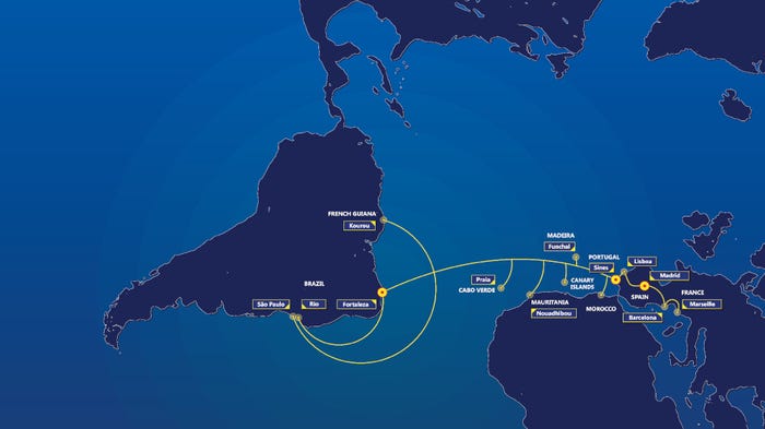
The latest fifth-generation submarine network transponders deliver the performance needed to close the additional optical paths out to the data center and active, intelligent power management provides the all-optical demarcation point as well as ensures optical service stability for all service types.
The value of open cables has been established for almost a decade, and the additional advantages of granular, all-optical spectrum sharing become increasingly attractive as fiber capacity levels rise into the tens of terabits range.
 Vincent Gatineau is the Chief Marketing and Sales Officer for EllaLink. Vincent has been part of the Sales & Marketing team of Alcatel Submarine Networks for 9 years, following the EllaLink project since its first days among other major systems developments. Previously, Vincent has held various international positions within the Alcatel-Lucent group in India and Chile. Vincent has an engineering degree from Institut Mines Telecom Lille Douai. He is fluent in French, English and Spanish.
 Geoff Bennett is the Director of Solutions & Technology for Infinera. He has over 25 years of experience in the data communications industry, including IP routing with Proteon and Wellfleet; ATM and MPLS experience with FORE Systems; and optical transmission and switching experience with Marconi, where he held the position of Distinguished Engineer in the CTO Office.
Read more about:
DiscussionAbout the Author(s)
You May Also Like


_1.jpg?width=700&auto=webp&quality=80&disable=upscale)


.png?width=800&auto=webp&quality=80&disable=upscale)